Ok folks I have finished the servo coolant nozzle screen set for Mach3. So far it has been working pretty good.
When I installed it on the ORK mill, I got my tool off set measurements wrong. It drove me nuts for an hour or two. I was thinking, Gosh it worked perfect on my cardboard testing setup. Here I was measuring the tool length from the flange instead of the difference between my zero tool and current tool. Have been doing other things besides machining and forgot.
I tried my best to make it easy to install. The screen set folder contains a few setting pictures and installing directions. There are two options in the nozzle parking Brains Ver1 and Ver2. Ver2 is the default and has a more positive, solid action. Some of the arduino code needs to be changed for Ver1 to work correctly. There is a note pad file in the screen set folder with all the details.
From this project, I have learned a lot about screen sets, brains, Arduino programming, Modbus, Inkscape and trigonometry. At times I felt like my brain was going to explode.
Here is a couple of videos showing how things work. Any questions can be left here, the CNC zone thread or on my Youtube channel. Have fun and be safe :)
The pictures below show the skinning of the front bulkhead. Since the walls will be assembled later the corners and edges need to be flat and even. The fabric is placed over the wall, half of it is folded back and glue is applied. Then it is placed back over the glue and pressed down with an iron on the lowest heat setting. This technique as also used to apply the inside fabric and the builders paper.
Tape is used to make clean strait edges. Excess is trimmed off
flip over fabric edge
applying tightbond 2 glue
Fold at edge of the tape
add more glue to folded edge
press flat with iron and remove tape
finished corner nice and flat to screw to the floor section.
inside of front wall
outer skin, just need to apply more Tightbond 2 that will
soak in and give a hard surface finish.
After many years of packing my car full to travel to archery festivals, I decided it's time to build
a small travel trailer. This way I can load up the trailer with gear, have a galley for cooking and a warm place to sleep. Oh yeah, so i can bring more fire wood, the Denton hill shoot was really cold this year and the camp mack shoot is always cold.
The camper is made to slide on to a 4X8 foot utility trailer. Weight is my biggest factor in the build. It is going to made with pine framing with foam cores and covered with fabric and glue. It is designed with a pop up roof and the left side folds down to in crease the sleeping area. When traveling it can be used with out opening the top or side bunk, (like a couple of hours sleep at a wallmart parking lot).
Since I don't have a garage it will be built in my basement in pieces over the winter and assembled out side in the spring. The parts will be left and right walls, front wall, roof, galley and floor.
right side showing galley an entry door
left side showing fold down bunk and pop up top
unfinished boards from old skids that were used in shipping new
chicken house equipment
ripped and planed boards.They were left to dry out for a month or two,measured and
checked for shrinkage.
Floor with foam core to add strength, new materials were used
in this part. I for got to rip the boards to a wider width.
top floor showing storage holes. The covering was trimmed
with a router
front bulk head
covered in builders paper
right side
covered in paper
The inside is covered with old table cloths I had laying around
coated and sealed with acrylic paint with no pigment added
More ideas keep popping in my my head for the nozzle screen set. The use of modbus has enabled me to implement more features. May not need them all but they are there if I need them.
Features:
1) auto tracking of depth of cut
2) auto aim at bottom of tool
3) air cleaning of tool
4) air blast nozzles
5) auto park of nozzles at tool change
6) sweep function
7) special function for up to 6 tools (combinations of 1 through 6)
To the right is the special function page. When the tool number DRO matches the number on this page it will automatically run the combinations in the table. The number of tools can be increased to more than 6, but the brain gets hard to see after a curtain size. The default is (0) so if a job uses 10 tools and 4 of them use the auto tracking for depth of cut this works out OK.
The sweep column is for setting the angle of sweep from the bottom of the tool.
The page to the left is same as before with some extra DRO's for the auto aim at the bottom of tool.
To the right is the brain that controls the auto tracking of the right side. This has 3 trig functions to triangulate the the angle of the nozzle. The number of brains are adding up I think there around 8 of them. Some are simple and some have up to 20+ inputs.
Its also easier to keep things more organized by breaking things down to smaller separate functions.
There is also the arduino sketch that keeps growing. but that's for a different post latter on.
Below is a video of how the set up page and controls work.
Wiring of servo power supply. The capacitors are a little over kill,but help filter out noise. In the video I'm using a 9 volt wall wort. On the machine it is a 12 volt din rail power supply.
With the capability of using modbus with the arduino. I can now get rid of the knobs on the control pannel. They will now reside in the mach3 screen set with a set up page. This way less wiring and hard ware is needed. The set up page will allow the system to be adapted to almost any mill using mach3. My goal is to make it an easy DIY project
I'm thinking of making a couple of different screen sets from basic auto aim to air blast options.
setup and main page
So far I have the setup page and the brains are done. The brain contains three trigonometry functions to adjust the nozzle angles automatically according to tool depth,length and width. When drilling or slotting the nozzle will stay at the top of the part being machined.
So after many months of research, reading ,trial and error. I finally got the servo coolant nozzles to be controlled directly by mach3. For testing a modbus sketch from the mach3 site was modified. A brain was created with a( DRO input>some math>modbus output) Now it seems very simple. I think most of my problems came from being new at all this. The pieces slowly came together and poof it started working.
With this more functions can be added like automatic adjusting for depth of cutting and drilling. Even for the width of the cutter. I can also get rid of the switch that controls tool cleaning function by sending the Zaxis height and tool change info to the arduino.
My plan is to redo the shield, putting all the components on one board. It will be relocated to the CNC control panel.
Will contain.
2 out puts for air solenoids maybe 3.
2 rotary encoders with push buttons for adjustments instead of pots, can get rid of 2 of them this way.
2 pots for the air blast on and off.
passive components and connectors.
Arduino sketch.
/*
Modbus over serial line - RTU Slave Arduino Sketch
By Juan Pablo Zometa : jpmzometa@gmail.com
http://sites.google.com/site/jpmzometa/
and Samuel Marco: sammarcoarmengol@gmail.com
and Andras Tucsni.
These functions implement functions 3, 6, and 16 (read holding registers,
preset single register and preset multiple registers) of the
Modbus RTU Protocol, to be used over the Arduino serial connection.
This implementation DOES NOT fully comply with the Modbus specifications.
This Arduino adaptation is derived from the work
By P.Costigan email: phil@pcscada.com.au http://pcscada.com.au
These library of functions are designed to enable a program send and
receive data from a device that communicates using the Modbus protocol.
Copyright (C) 2000 Philip Costigan P.C. SCADA LINK PTY. LTD.
This program is free software; you can redistribute it and/or modify
it under the terms of the GNU General Public License as published by
the Free Software Foundation; either version 2 of the License, or
(at your option) any later version.
This program is distributed in the hope that it will be useful,
but WITHOUT ANY WARRANTY; without even the implied warranty of
MERCHANTABILITY or FITNESS FOR A PARTICULAR PURPOSE. See the
GNU General Public License for more details.
You should have received a copy of the GNU General Public License
along with this program; if not, write to the Free Software
Foundation, Inc., 675 Mass Ave, Cambridge, MA 02139, USA.
The functions included here have been derived from the
Modicon Modbus Protocol Reference Guide
which can be obtained from Schneider at www.schneiderautomation.com.
This code has its origins with
paul@pmcrae.freeserve.co.uk (http://www.pmcrae.freeserve.co.uk)
who wrote a small program to read 100 registers from a modbus slave.
I have used his code as a catalist to produce this more functional set
of functions. Thanks paul.
*/
/*
* configure_mb_slave(baud, parity, tx_en_pin)
*
* sets the communication parameters for of the serial line.
*
* baud: baudrate in bps (typical values 9600, 19200... 115200)
* parity: a single character sets the parity mode (character frame format):
* 'n' no parity (8N1); 'e' even parity (8E1), 'o' for odd parity (8O1).
* tx_en_pin: arduino pin number that controls transmision/reception
* of an external half-duplex device (e.g. a RS485 interface chip).
* 0 or 1 disables this function (for a two-device network)
* >2 for point-to-multipoint topology (e.g. several arduinos)
*/
/*
* update_mb_slave(slave_id, holding_regs_array, number_of_regs)
*
* checks if there is any valid request from the modbus master. If there is,
* performs the action requested
*
* slave: slave id (1 to 127)
* regs: an array with the holding registers. They start at address 1 (master point of view)
* regs_size: total number of holding registers.
* returns: 0 if no request from master,
* NO_REPLY (-1) if no reply is sent to the master
* an exception code (1 to 4) in case of a modbus exceptions
* the number of bytes sent as reply ( > 4) if OK.
*/
int update_mb_slave(unsigned char slave, int *regs,
unsigned int regs_size);
int t1,t2,t3,t4,t5 ;
/* Modbus RTU common parameters, the Master MUST use the same parameters */
enum {
MB_SLAVE = 1,/* modbus slave id */
};
/* slave registers example */
enum {
MB_REG0,
MB_REG1,
// line below is for holding registers. 'vinny'
MB_REGS= 40 /* total number of registers on slave */
};
int regs[MB_REGS];/* this is the slave's modbus data map */
Servo servo1; // create servo object to control a servo
Servo servo2;
int val; // variable to store the angle
void setup()
{
/* Modbus setup example, the master must use the same COM parameters */
/* 115200 bps, 8N1, two-device network */
// changed to 19200 bps, 8N1, two-device network 'vinny'
configure_mb_slave(9600, 'n', 1);
servo1.attach(9); // attaches the servo on pin 9 to the servo object
servo2.attach(10);
}
void loop()
{
/* This is all for the Modbus slave */ update_mb_slave(MB_SLAVE, regs, MB_REGS) ;
//regs[0]=analogRead(A0); commented out not used for coolant nozzles
//regs[1]=analogRead(A1); part of original sketch using pots for FRO
val=regs[0];
servo1.write(val); // sets the servo position according to the scaled value
servo2.write(val);
//delay(15);
}
/****************************************************************************
* BEGIN MODBUS RTU SLAVE FUNCTIONS
****************************************************************************/
/* global variables */
unsigned int Txenpin = 0; /* Enable transmission pin, used on RS485 networks */
/* enum of supported modbus function codes. If you implement a new one, put its function code here ! */
enum {
FC_READ_REGS = 0x03, //Read contiguous block of holding register
FC_WRITE_REG = 0x06, //Write single holding register
FC_WRITE_REGS = 0x10 //Write block of contiguous registers
};
/* supported functions. If you implement a new one, put its function code into this array! */
const unsigned char fsupported[] = { FC_READ_REGS, FC_WRITE_REG, FC_WRITE_REGS };
INPUTS: buf -> Array containing message to be sent to controller. start -> Start of loop in crc counter, usually 0. cnt -> Amount of bytes in message being sent to controller/
OUTPUTS: temp -> Returns crc byte for message.
COMMENTS: This routine calculates the crc high and low byte of a message. Note that this crc is only used for Modbus, not Modbus+ etc.
****************************************************************************/
unsigned int crc(unsigned char *buf, unsigned char start,
unsigned char cnt)
{
unsigned char i, j;
unsigned temp, temp2, flag;
temp = 0xFFFF;
for (i = start; i < cnt; i++) {
temp = temp ^ buf[i];
for (j = 1; j <= 8; j++) {
flag = temp & 0x0001;
temp = temp >> 1;
if (flag)
temp = temp ^ 0xA001;
}
}
/***********************************************************************
*
* The following functions construct the required query into
* a modbus query packet.
*
***********************************************************************/
/*
* Start of the packet of a read_holding_register response
*/
void build_read_packet(unsigned char slave, unsigned char function,
unsigned char count, unsigned char *packet)
{
packet[SLAVE] = slave;
packet[FUNC] = function;
packet[2] = count * 2;
}
/*
* Start of the packet of a write_single_register response
*/
void build_write_single_packet(unsigned char slave, unsigned char function,
unsigned int write_addr, unsigned int reg_val, unsigned char* packet)
{
packet[SLAVE] = slave;
packet[FUNC] = function;
packet[START_H] = write_addr >> 8;
packet[START_L] = write_addr & 0x00ff;
packet[REGS_H] = reg_val >> 8;
packet[REGS_L] = reg_val & 0x00ff;
}
/*
* Start of the packet of an exception response
*/
void build_error_packet(unsigned char slave, unsigned char function,
unsigned char exception, unsigned char *packet)
{
packet[SLAVE] = slave;
packet[FUNC] = function + 0x80;
packet[2] = exception;
}
/*************************************************************************
*
* modbus_query( packet, length)
*
* Function to add a checksum to the end of a packet.
* Please note that the packet array must be at least 2 fields longer than
* string_length.
**************************************************************************/
void modbus_reply(unsigned char *packet, unsigned char string_length)
{
int temp_crc;
/***********************************************************************
*
* send_reply( query_string, query_length )
*
* Function to send a reply to a modbus master.
* Returns: total number of characters sent
************************************************************************/
for (i = 0; i < string_length; i++) {
Serial.write(query[i]);
}
if (Txenpin > 1) {// set MAX485 to listen mode
while (!(UCSR0A & (1 << TXC0)));
digitalWrite( Txenpin, LOW);
}
return i; /* it does not mean that the write was succesful, though */
}
/***********************************************************************
*
* receive_request( array_for_data )
*
* Function to monitor for a request from the modbus master.
*
* Returns:Total number of characters received if OK
* 0 if there is no request
* A negative error code on failure
***********************************************************************/
int receive_request(unsigned char *received_string)
{
int bytes_received = 0;
/* FIXME: does Serial.available wait 1.5T or 3.5T before exiting the loop? */
while (Serial.available()) {
received_string[bytes_received] = Serial.read();
bytes_received++;
if (bytes_received >= MAX_MESSAGE_LENGTH)
return NO_REPLY; /* port error */
}
return (bytes_received);
}
/*********************************************************************
*
* modbus_request(slave_id, request_data_array)
*
* Function to the correct request is returned and that the checksum
* is correct.
*
* Returns:string_length if OK
* 0 if failed
* Less than 0 for exception errors
*
* Note: All functions used for sending or receiving data via
* modbus return these return values.
*
**********************************************************************/
int modbus_request(unsigned char slave, unsigned char *data)
{
int response_length;
unsigned int crc_calc = 0;
unsigned int crc_received = 0;
unsigned char recv_crc_hi;
unsigned char recv_crc_lo;
/*********** check CRC of response ************/
if (crc_calc != crc_received) {
return NO_REPLY;
}
/* check for slave id */
if (slave != data[SLAVE]) {
return NO_REPLY;
}
}
return (response_length);
}
/*********************************************************************
*
* validate_request(request_data_array, request_length, available_regs)
*
* Function to check that the request can be processed by the slave.
*
* Returns:0 if OK
* A negative exception code on error
*
**********************************************************************/
int validate_request(unsigned char *data, unsigned char length,
unsigned int regs_size)
{
int i, fcnt = 0;
unsigned int regs_num = 0;
unsigned int start_addr = 0;
unsigned char max_regs_num;
/* check function code */
for (i = 0; i < sizeof(fsupported); i++) {
if (fsupported[i] == data[FUNC]) {
fcnt = 1;
break;
}
}
if (0 == fcnt)
return EXC_FUNC_CODE;
if (FC_WRITE_REG == data[FUNC]) {
/* For function write single reg, this is the target reg.*/
regs_num = ((int) data[START_H] << 8) + (int) data[START_L];
if (regs_num >= regs_size)
return EXC_ADDR_RANGE;
return 0;
}
/* For functions read/write regs, this is the range. */
regs_num = ((int) data[REGS_H] << 8) + (int) data[REGS_L];
/* check quantity of registers */
if (FC_READ_REGS == data[FUNC])
max_regs_num = MAX_READ_REGS;
else if (FC_WRITE_REGS == data[FUNC])
max_regs_num = MAX_WRITE_REGS;
if ((regs_num < 1) || (regs_num > max_regs_num))
return EXC_REGS_QUANT;
/************************************************************************
*
* write_regs(first_register, data_array, registers_array)
*
* writes into the slave's holding registers the data in query,
* starting at start_addr.
*
* Returns: the number of registers written
************************************************************************/
int write_regs(unsigned int start_addr, unsigned char *query, int *regs)
{
int temp;
unsigned int i;
for (i = 0; i < query[REGS_L]; i++) {
/* shift reg hi_byte to temp */
temp = (int) query[(BYTE_CNT + 1) + i * 2] << 8;
/* OR with lo_byte */
temp = temp | (int) query[(BYTE_CNT + 2) + i * 2];
regs[start_addr + i] = temp;
}
return i;
}
/************************************************************************
*
* preset_multiple_registers(slave_id, first_register, number_of_registers,
* data_array, registers_array)
*
* Write the data from an array into the holding registers of the slave.
*
*************************************************************************/
int preset_multiple_registers(unsigned char slave,
unsigned int start_addr,
unsigned char count,
unsigned char *query,
int *regs)
{
unsigned char function = FC_WRITE_REGS;/* Preset Multiple Registers */
int status = 0;
unsigned char packet[RESPONSE_SIZE + CHECKSUM_SIZE];
if (write_regs(start_addr, query, regs)) {
status = send_reply(packet, RESPONSE_SIZE);
}
return (status);
}
/************************************************************************
*
* write_single_register(slave_id, write_addr, data_array, registers_array)
*
* Write a single int val into a single holding register of the slave.
*
*************************************************************************/
int write_single_register(unsigned char slave,
unsigned int write_addr, unsigned char *query, int *regs)
{
unsigned char function = FC_WRITE_REG; /* Function: Write Single Register */
int status = 0;
unsigned int reg_val;
unsigned char packet[RESPONSE_SIZE + CHECKSUM_SIZE];
/************************************************************************
*
* read_holding_registers(slave_id, first_register, number_of_registers,
* registers_array)
*
* reads the slave's holdings registers and sends them to the Modbus master
*
*************************************************************************/
int read_holding_registers(unsigned char slave, unsigned int start_addr,
unsigned char reg_count, int *regs)
{
unsigned char function = 0x03; /* Function 03: Read Holding Registers */
int packet_size = 3;
int status;
unsigned int i;
unsigned char packet[MAX_MESSAGE_LENGTH];
if (txenpin > 1) { // pin 0 & pin 1 are reserved for RX/TX
Txenpin = txenpin; /* set global variable */
pinMode(Txenpin, OUTPUT);
digitalWrite(Txenpin, LOW);
}
return;
}
/*
* update_mb_slave(slave_id, holding_regs_array, number_of_regs)
*
* checks if there is any valid request from the modbus master. If there is,
* performs the action requested
*/
unsigned long Nowdt = 0;
unsigned int lastBytesReceived;
const unsigned long T35 = 5;
int update_mb_slave(unsigned char slave, int *regs,
unsigned int regs_size)
{
unsigned char query[MAX_MESSAGE_LENGTH];
unsigned char errpacket[EXCEPTION_SIZE + CHECKSUM_SIZE];
unsigned int start_addr;
int exception;
int length = Serial.available();
unsigned long now = millis();
Have been refining the design of the power draw bar. I'm try to simplify and lower the number of parts as much as possible. I figured the guide rods could be eliminated by strengthening linear actuator. The impact socket will be used to retract the spindle lock instead of the long bolts on the sides.
The linear actuator will use a 3/8 screw, so i can have many options. (3/8-16, 3/8-24, 3/8-8 acme.3/8-10 acme, 3/8-12 acme). The over run spring for the actuator has been moved to the screw nut instead at the bottom. This is to make it more rigid and simpler to machine the part, plus removing the guide rod made it a must.
The spindle lock be two interlocking dogs. In the bottom lock dog the draw bar will be "captured" to eliminate a sticking collet from driving back and damaging something.
A 12 point nut and socket will make engagement more reliable. On my current system system things don't always the first time.
In theory this is how it will work.
Step 1 linear actuator moves down. (push out button)
Step 2 if socket does not engage the spring inside actuator will compensate
Step 3 slowly turn motor
Step 4 socket engages nut (switch will verify this)
Step 5 keep slowly turn motor ( this will turn the spindle)
Step 6 lock dogs will engage (switch will verify this)
Step 7 increase motor speed in reverse to loosen
Step 8 change tool (my job)
Step 9 increase motor speed forward to tighten (push in button)
Step 10 move linear actuator up, socket will pull the lock dogs apart.
Finished machining the coolant nozzle this past weekend. The hub has a push to connect fitting so different size nozzles can be quickly changed. There are also three places to attach air nozzles or other future attachments.
The hub was designed in sketchup after messing up the first one due to operator error. The second one turned out to be a much better design.
Fancy nozzle
Large .5 inch nozzle
Extra long nozzle
Disassembled showing all the parts. The round part on the right is the first hub I made. I messed the part up by not having the origin correct.
The progress has been slow on my updated coolant nozzles. I took my original DXF drawings that were made in Delta cad and imported them into Sketchup8. Working in 3D is a lot better than the 2D cad.
I call this the howitzer nozzle because main nozzle will be .5" inches in diameter. There will also be three places to attach other types of air nozzles. Plus the main nozzle will use a push to connect fitting to make swapping out different size and shape nozzles easier. This will replace one of my current RC servo powered system. To see them working check out my youtube channel. https://www.youtube.com/channel/UCcIK-PynOymd_15wWIhGyHg
These are the parts made from the original 2D DXF drawings. The only part left to make is main nozzle assembly. (the light green part)
Spent the weekend using sketchup8 designing a new power draw bar for the ORK mill. My goal is to make my current electric impact draw bar a push button operated system, with out using any pneumatics. Instead of an air cylinder to engage the impact wrench I plan to make a linear actuator. I was thinking of using a Fergelli L16 or L12 linear actuator. But at 80.00 a piece, plus the control board and the possibility of breaking the plastic ends put them out of my price range.
The diy linear actuator will be powered by a small gear motor and controlled by an h bridge/RC servo board circuit from the website, lets make robots . A 50amp smart car h bridge will control the direction and speed of the impact wrench. In the picture below the thin plate is a pcb that will contain a diy arduino , relays and the tactile switches. I'm not sure about the LCD display yet, I might eliminate it, to simplify the design. The switch panel is made in inkscape then printed, laminated and placed over the tactile switches to make it coolant proof .
The light blue pins will engage a locking ring on the spindle, may not need this part, will try it without it.
Trying to make it a simple add on, with out having to much wiring integrated in to the main system. The arduino sketch will have a jiggle feature to help align the nut and spindle lock, with a time out function. Will also add a circuit to put the machine in E stop when the draw bar is engaged or if there is a malfunction. Don't want an Oooop!!! moment.
Added some electronics from the sketchup warehouse to the pcb. Used the x-ray function to check to
make sure every thing fits.
Not much has been going on in the shop lately because it has been so F*&%$ cold. But a friend asked me to make some slot car pinion gears. I used to make them on a manual mill drill years ago. It was very time consuming. The shoulder and axle hole are still done manually,some day I will build a CNC lathe.
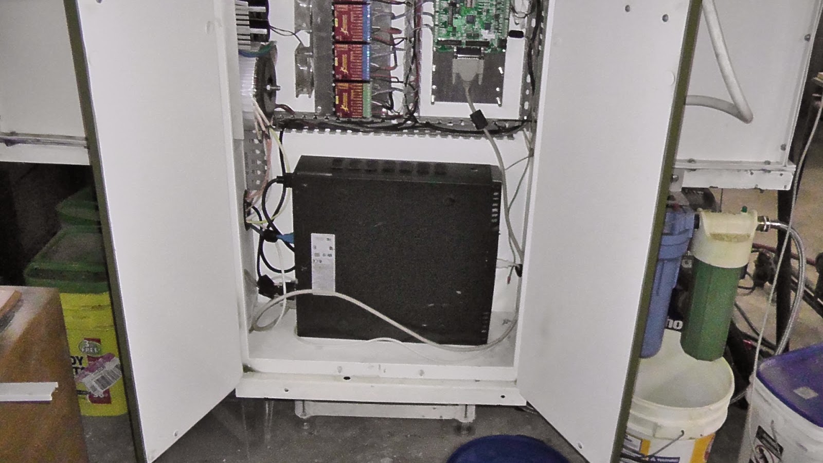
So I fired up the CNC mill and nothing happened, the 12 year old PC mother board died. I took the hard drive (was only three years old) and RAM out and installed it in an Compaq PC that i picked up along road for free. Installed Mach3 and screen sets, but my configuration save file was not up dated since the mill was built years ago. No settings were saved for the spindle,4th axis, tool change macros and screen settings. My advice is make sure you save a config file each time the mill is upgraded.
new PC, a little smaller than the old one
old PC
Oh yeah,I almost forgot about the slot car gears. Just .3125 inches in diameter with 15 teeth for the rear axle. I don't know what type of car they fit, I just make them. Will add a machining video later.