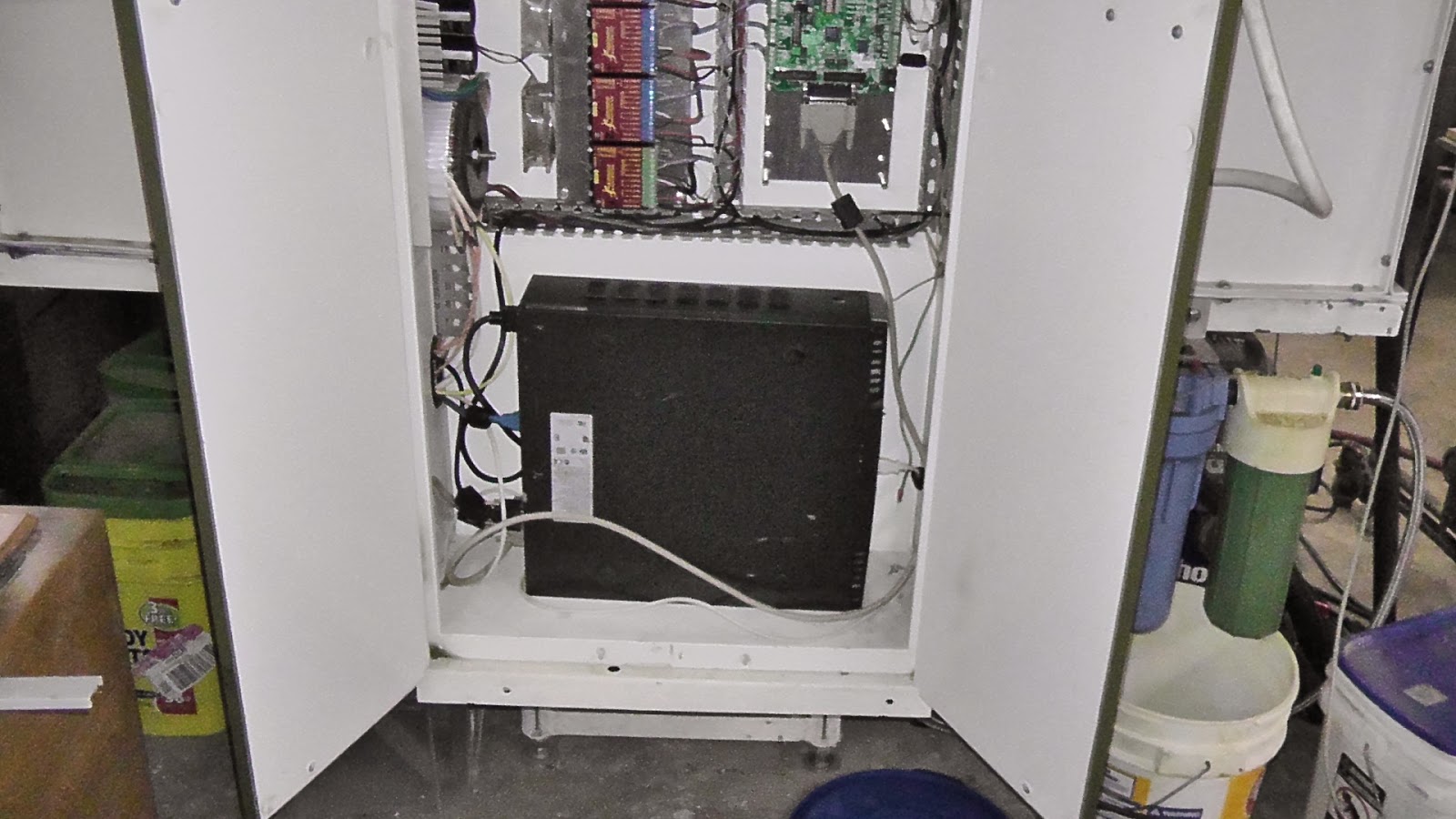
With this more functions can be added like automatic adjusting for depth of cutting and drilling. Even for the width of the cutter. I can also get rid of the switch that controls tool cleaning function by sending the Zaxis height and tool change info to the arduino.
My plan is to redo the shield, putting all the components on one board. It will be relocated to the CNC control panel.
Will contain.
2 out puts for air solenoids maybe 3.
2 rotary encoders with push buttons for adjustments instead of pots, can get rid of 2 of them this way.
2 pots for the air blast on and off.
passive components and connectors.
Arduino sketch.
/*
Modbus over serial line - RTU Slave Arduino Sketch
By Juan Pablo Zometa : jpmzometa@gmail.com
http://sites.google.com/site/jpmzometa/
and Samuel Marco: sammarcoarmengol@gmail.com
and Andras Tucsni.
These functions implement functions 3, 6, and 16 (read holding registers,
preset single register and preset multiple registers) of the
Modbus RTU Protocol, to be used over the Arduino serial connection.
This implementation DOES NOT fully comply with the Modbus specifications.
This Arduino adaptation is derived from the work
By P.Costigan email: phil@pcscada.com.au http://pcscada.com.au
These library of functions are designed to enable a program send and
receive data from a device that communicates using the Modbus protocol.
Copyright (C) 2000 Philip Costigan P.C. SCADA LINK PTY. LTD.
This program is free software; you can redistribute it and/or modify
it under the terms of the GNU General Public License as published by
the Free Software Foundation; either version 2 of the License, or
(at your option) any later version.
This program is distributed in the hope that it will be useful,
but WITHOUT ANY WARRANTY; without even the implied warranty of
MERCHANTABILITY or FITNESS FOR A PARTICULAR PURPOSE. See the
GNU General Public License for more details.
You should have received a copy of the GNU General Public License
along with this program; if not, write to the Free Software
Foundation, Inc., 675 Mass Ave, Cambridge, MA 02139, USA.
The functions included here have been derived from the
Modicon Modbus Protocol Reference Guide
which can be obtained from Schneider at www.schneiderautomation.com.
This code has its origins with
paul@pmcrae.freeserve.co.uk (http://www.pmcrae.freeserve.co.uk)
who wrote a small program to read 100 registers from a modbus slave.
I have used his code as a catalist to produce this more functional set
of functions. Thanks paul.
*/
/*
* configure_mb_slave(baud, parity, tx_en_pin)
*
* sets the communication parameters for of the serial line.
*
* baud: baudrate in bps (typical values 9600, 19200... 115200)
* parity: a single character sets the parity mode (character frame format):
* 'n' no parity (8N1); 'e' even parity (8E1), 'o' for odd parity (8O1).
* tx_en_pin: arduino pin number that controls transmision/reception
* of an external half-duplex device (e.g. a RS485 interface chip).
* 0 or 1 disables this function (for a two-device network)
* >2 for point-to-multipoint topology (e.g. several arduinos)
*/
#include <Servo.h>
void configure_mb_slave(long baud, char parity, char txenpin);
/*
* update_mb_slave(slave_id, holding_regs_array, number_of_regs)
*
* checks if there is any valid request from the modbus master. If there is,
* performs the action requested
*
* slave: slave id (1 to 127)
* regs: an array with the holding registers. They start at address 1 (master point of view)
* regs_size: total number of holding registers.
* returns: 0 if no request from master,
* NO_REPLY (-1) if no reply is sent to the master
* an exception code (1 to 4) in case of a modbus exceptions
* the number of bytes sent as reply ( > 4) if OK.
*/
int update_mb_slave(unsigned char slave, int *regs,
unsigned int regs_size);
int t1,t2,t3,t4,t5 ;
/* Modbus RTU common parameters, the Master MUST use the same parameters */
enum {
MB_SLAVE = 1, /* modbus slave id */
};
/* slave registers example */
enum {
MB_REG0,
MB_REG1,
// line below is for holding registers. 'vinny'
MB_REGS = 40 /* total number of registers on slave */
};
int regs[MB_REGS]; /* this is the slave's modbus data map */
Servo servo1; // create servo object to control a servo
Servo servo2;
int val; // variable to store the angle
void setup()
{
/* Modbus setup example, the master must use the same COM parameters */
/* 115200 bps, 8N1, two-device network */
// changed to 19200 bps, 8N1, two-device network 'vinny'
configure_mb_slave(9600, 'n', 1);
servo1.attach(9); // attaches the servo on pin 9 to the servo object
servo2.attach(10);
}
void loop()
{
/* This is all for the Modbus slave */
update_mb_slave(MB_SLAVE, regs, MB_REGS) ;
//regs[0]=analogRead(A0); commented out not used for coolant nozzles
//regs[1]=analogRead(A1); part of original sketch using pots for FRO
val=regs[0];
servo1.write(val); // sets the servo position according to the scaled value
servo2.write(val);
//delay(15);
}
/****************************************************************************
* BEGIN MODBUS RTU SLAVE FUNCTIONS
****************************************************************************/
/* global variables */
unsigned int Txenpin = 0; /* Enable transmission pin, used on RS485 networks */
/* enum of supported modbus function codes. If you implement a new one, put its function code here ! */
enum {
FC_READ_REGS = 0x03, //Read contiguous block of holding register
FC_WRITE_REG = 0x06, //Write single holding register
FC_WRITE_REGS = 0x10 //Write block of contiguous registers
};
/* supported functions. If you implement a new one, put its function code into this array! */
const unsigned char fsupported[] = { FC_READ_REGS, FC_WRITE_REG, FC_WRITE_REGS };
/* constants */
enum {
MAX_READ_REGS = 0x7D,
MAX_WRITE_REGS = 0x7B,
MAX_MESSAGE_LENGTH = 256
};
enum {
RESPONSE_SIZE = 6,
EXCEPTION_SIZE = 3,
CHECKSUM_SIZE = 2
};
/* exceptions code */
enum {
NO_REPLY = -1,
EXC_FUNC_CODE = 1,
EXC_ADDR_RANGE = 2,
EXC_REGS_QUANT = 3,
EXC_EXECUTE = 4
};
/* positions inside the query/response array */
enum {
SLAVE = 0,
FUNC,
START_H,
START_L,
REGS_H,
REGS_L,
BYTE_CNT
};
/*
CRC
INPUTS:
buf -> Array containing message to be sent to controller.
start -> Start of loop in crc counter, usually 0.
cnt -> Amount of bytes in message being sent to controller/
OUTPUTS:
temp -> Returns crc byte for message.
COMMENTS:
This routine calculates the crc high and low byte of a message.
Note that this crc is only used for Modbus, not Modbus+ etc.
****************************************************************************/
unsigned int crc(unsigned char *buf, unsigned char start,
unsigned char cnt)
{
unsigned char i, j;
unsigned temp, temp2, flag;
temp = 0xFFFF;
for (i = start; i < cnt; i++) {
temp = temp ^ buf[i];
for (j = 1; j <= 8; j++) {
flag = temp & 0x0001;
temp = temp >> 1;
if (flag)
temp = temp ^ 0xA001;
}
}
/* Reverse byte order. */
temp2 = temp >> 8;
temp = (temp << 8) | temp2;
temp &= 0xFFFF;
return (temp);
}
/***********************************************************************
*
* The following functions construct the required query into
* a modbus query packet.
*
***********************************************************************/
/*
* Start of the packet of a read_holding_register response
*/
void build_read_packet(unsigned char slave, unsigned char function,
unsigned char count, unsigned char *packet)
{
packet[SLAVE] = slave;
packet[FUNC] = function;
packet[2] = count * 2;
}
/*
* Start of the packet of a preset_multiple_register response
*/
void build_write_packet(unsigned char slave, unsigned char function,
unsigned int start_addr,
unsigned char count,
unsigned char *packet)
{
packet[SLAVE] = slave;
packet[FUNC] = function;
packet[START_H] = start_addr >> 8;
packet[START_L] = start_addr & 0x00ff;
packet[REGS_H] = 0x00;
packet[REGS_L] = count;
}
/*
* Start of the packet of a write_single_register response
*/
void build_write_single_packet(unsigned char slave, unsigned char function,
unsigned int write_addr, unsigned int reg_val, unsigned char* packet)
{
packet[SLAVE] = slave;
packet[FUNC] = function;
packet[START_H] = write_addr >> 8;
packet[START_L] = write_addr & 0x00ff;
packet[REGS_H] = reg_val >> 8;
packet[REGS_L] = reg_val & 0x00ff;
}
/*
* Start of the packet of an exception response
*/
void build_error_packet(unsigned char slave, unsigned char function,
unsigned char exception, unsigned char *packet)
{
packet[SLAVE] = slave;
packet[FUNC] = function + 0x80;
packet[2] = exception;
}
/*************************************************************************
*
* modbus_query( packet, length)
*
* Function to add a checksum to the end of a packet.
* Please note that the packet array must be at least 2 fields longer than
* string_length.
**************************************************************************/
void modbus_reply(unsigned char *packet, unsigned char string_length)
{
int temp_crc;
temp_crc = crc(packet, 0, string_length);
packet[string_length] = temp_crc >> 8;
string_length++;
packet[string_length] = temp_crc & 0x00FF;
}
/***********************************************************************
*
* send_reply( query_string, query_length )
*
* Function to send a reply to a modbus master.
* Returns: total number of characters sent
************************************************************************/
int send_reply(unsigned char *query, unsigned char string_length)
{
unsigned char i;
if (Txenpin > 1) { // set MAX485 to speak mode
UCSR0A=UCSR0A |(1 << TXC0);
digitalWrite( Txenpin, HIGH);
delay(1);
}
modbus_reply(query, string_length);
string_length += 2;
for (i = 0; i < string_length; i++) {
Serial.write(query[i]);
}
if (Txenpin > 1) {// set MAX485 to listen mode
while (!(UCSR0A & (1 << TXC0)));
digitalWrite( Txenpin, LOW);
}
return i; /* it does not mean that the write was succesful, though */
}
/***********************************************************************
*
* receive_request( array_for_data )
*
* Function to monitor for a request from the modbus master.
*
* Returns: Total number of characters received if OK
* 0 if there is no request
* A negative error code on failure
***********************************************************************/
int receive_request(unsigned char *received_string)
{
int bytes_received = 0;
/* FIXME: does Serial.available wait 1.5T or 3.5T before exiting the loop? */
while (Serial.available()) {
received_string[bytes_received] = Serial.read();
bytes_received++;
if (bytes_received >= MAX_MESSAGE_LENGTH)
return NO_REPLY; /* port error */
}
return (bytes_received);
}
/*********************************************************************
*
* modbus_request(slave_id, request_data_array)
*
* Function to the correct request is returned and that the checksum
* is correct.
*
* Returns: string_length if OK
* 0 if failed
* Less than 0 for exception errors
*
* Note: All functions used for sending or receiving data via
* modbus return these return values.
*
**********************************************************************/
int modbus_request(unsigned char slave, unsigned char *data)
{
int response_length;
unsigned int crc_calc = 0;
unsigned int crc_received = 0;
unsigned char recv_crc_hi;
unsigned char recv_crc_lo;
response_length = receive_request(data);
if (response_length > 0) {
crc_calc = crc(data, 0, response_length - 2);
recv_crc_hi = (unsigned) data[response_length - 2];
recv_crc_lo = (unsigned) data[response_length - 1];
crc_received = data[response_length - 2];
crc_received = (unsigned) crc_received << 8;
crc_received =
crc_received | (unsigned) data[response_length - 1];
/*********** check CRC of response ************/
if (crc_calc != crc_received) {
return NO_REPLY;
}
/* check for slave id */
if (slave != data[SLAVE]) {
return NO_REPLY;
}
}
return (response_length);
}
/*********************************************************************
*
* validate_request(request_data_array, request_length, available_regs)
*
* Function to check that the request can be processed by the slave.
*
* Returns: 0 if OK
* A negative exception code on error
*
**********************************************************************/
int validate_request(unsigned char *data, unsigned char length,
unsigned int regs_size)
{
int i, fcnt = 0;
unsigned int regs_num = 0;
unsigned int start_addr = 0;
unsigned char max_regs_num;
/* check function code */
for (i = 0; i < sizeof(fsupported); i++) {
if (fsupported[i] == data[FUNC]) {
fcnt = 1;
break;
}
}
if (0 == fcnt)
return EXC_FUNC_CODE;
if (FC_WRITE_REG == data[FUNC]) {
/* For function write single reg, this is the target reg.*/
regs_num = ((int) data[START_H] << 8) + (int) data[START_L];
if (regs_num >= regs_size)
return EXC_ADDR_RANGE;
return 0;
}
/* For functions read/write regs, this is the range. */
regs_num = ((int) data[REGS_H] << 8) + (int) data[REGS_L];
/* check quantity of registers */
if (FC_READ_REGS == data[FUNC])
max_regs_num = MAX_READ_REGS;
else if (FC_WRITE_REGS == data[FUNC])
max_regs_num = MAX_WRITE_REGS;
if ((regs_num < 1) || (regs_num > max_regs_num))
return EXC_REGS_QUANT;
/* check registers range, start address is 0 */
start_addr = ((int) data[START_H] << 8) + (int) data[START_L];
if ((start_addr + regs_num) > regs_size)
return EXC_ADDR_RANGE;
return 0; /* OK, no exception */
}
/************************************************************************
*
* write_regs(first_register, data_array, registers_array)
*
* writes into the slave's holding registers the data in query,
* starting at start_addr.
*
* Returns: the number of registers written
************************************************************************/
int write_regs(unsigned int start_addr, unsigned char *query, int *regs)
{
int temp;
unsigned int i;
for (i = 0; i < query[REGS_L]; i++) {
/* shift reg hi_byte to temp */
temp = (int) query[(BYTE_CNT + 1) + i * 2] << 8;
/* OR with lo_byte */
temp = temp | (int) query[(BYTE_CNT + 2) + i * 2];
regs[start_addr + i] = temp;
}
return i;
}
/************************************************************************
*
* preset_multiple_registers(slave_id, first_register, number_of_registers,
* data_array, registers_array)
*
* Write the data from an array into the holding registers of the slave.
*
*************************************************************************/
int preset_multiple_registers(unsigned char slave,
unsigned int start_addr,
unsigned char count,
unsigned char *query,
int *regs)
{
unsigned char function = FC_WRITE_REGS; /* Preset Multiple Registers */
int status = 0;
unsigned char packet[RESPONSE_SIZE + CHECKSUM_SIZE];
build_write_packet(slave, function, start_addr, count, packet);
if (write_regs(start_addr, query, regs)) {
status = send_reply(packet, RESPONSE_SIZE);
}
return (status);
}
/************************************************************************
*
* write_single_register(slave_id, write_addr, data_array, registers_array)
*
* Write a single int val into a single holding register of the slave.
*
*************************************************************************/
int write_single_register(unsigned char slave,
unsigned int write_addr, unsigned char *query, int *regs)
{
unsigned char function = FC_WRITE_REG; /* Function: Write Single Register */
int status = 0;
unsigned int reg_val;
unsigned char packet[RESPONSE_SIZE + CHECKSUM_SIZE];
reg_val = query[REGS_H] << 8 | query[REGS_L];
build_write_single_packet(slave, function, write_addr, reg_val, packet);
regs[write_addr] = (int) reg_val;
/*
written.start_addr=write_addr;
written.num_regs=1;
*/
status = send_reply(packet, RESPONSE_SIZE);
return (status);
}
/************************************************************************
*
* read_holding_registers(slave_id, first_register, number_of_registers,
* registers_array)
*
* reads the slave's holdings registers and sends them to the Modbus master
*
*************************************************************************/
int read_holding_registers(unsigned char slave, unsigned int start_addr,
unsigned char reg_count, int *regs)
{
unsigned char function = 0x03; /* Function 03: Read Holding Registers */
int packet_size = 3;
int status;
unsigned int i;
unsigned char packet[MAX_MESSAGE_LENGTH];
build_read_packet(slave, function, reg_count, packet);
for (i = start_addr; i < (start_addr + (unsigned int) reg_count);
i++) {
packet[packet_size] = regs[i] >> 8;
packet_size++;
packet[packet_size] = regs[i] & 0x00FF;
packet_size++;
}
status = send_reply(packet, packet_size);
return (status);
}
void configure_mb_slave(long baud, char parity, char txenpin)
{
Serial.begin(baud);
switch (parity) {
case 'e': // 8E1
UCSR0C |= ((1<<UPM01) | (1<<UCSZ01) | (1<<UCSZ00));
// UCSR0C &= ~((1<<UPM00) | (1<<UCSZ02) | (1<<USBS0));
break;
case 'o': // 8O1
UCSR0C |= ((1<<UPM01) | (1<<UPM00) | (1<<UCSZ01) | (1<<UCSZ00));
// UCSR0C &= ~((1<<UCSZ02) | (1<<USBS0));
break;
case 'n': // 8N1
UCSR0C |= ((1<<UCSZ01) | (1<<UCSZ00));
// UCSR0C &= ~((1<<UPM01) | (1<<UPM00) | (1<<UCSZ02) | (1<<USBS0));
break;
default:
break;
}
if (txenpin > 1) { // pin 0 & pin 1 are reserved for RX/TX
Txenpin = txenpin; /* set global variable */
pinMode(Txenpin, OUTPUT);
digitalWrite(Txenpin, LOW);
}
return;
}
/*
* update_mb_slave(slave_id, holding_regs_array, number_of_regs)
*
* checks if there is any valid request from the modbus master. If there is,
* performs the action requested
*/
unsigned long Nowdt = 0;
unsigned int lastBytesReceived;
const unsigned long T35 = 5;
int update_mb_slave(unsigned char slave, int *regs,
unsigned int regs_size)
{
unsigned char query[MAX_MESSAGE_LENGTH];
unsigned char errpacket[EXCEPTION_SIZE + CHECKSUM_SIZE];
unsigned int start_addr;
int exception;
int length = Serial.available();
unsigned long now = millis();
if (length == 0) {
lastBytesReceived = 0;
return 0;
}
if (lastBytesReceived != length) {
lastBytesReceived = length;
Nowdt = now + T35;
return 0;
}
if (now < Nowdt)
return 0;
lastBytesReceived = 0;
length = modbus_request(slave, query);
if (length < 1)
return length;
exception = validate_request(query, length, regs_size);
if (exception) {
build_error_packet(slave, query[FUNC], exception,
errpacket);
send_reply(errpacket, EXCEPTION_SIZE);
return (exception);
}
start_addr = ((int) query[START_H] << 8) +
(int) query[START_L];
switch (query[FUNC]) {
case FC_READ_REGS:
return read_holding_registers(slave,
start_addr,
query[REGS_L],
regs);
break;
case FC_WRITE_REGS:
return preset_multiple_registers(slave,
start_addr,
query[REGS_L],
query,
regs);
break;
case FC_WRITE_REG:
write_single_register(slave,
start_addr,
query,
regs);
break;
}
}